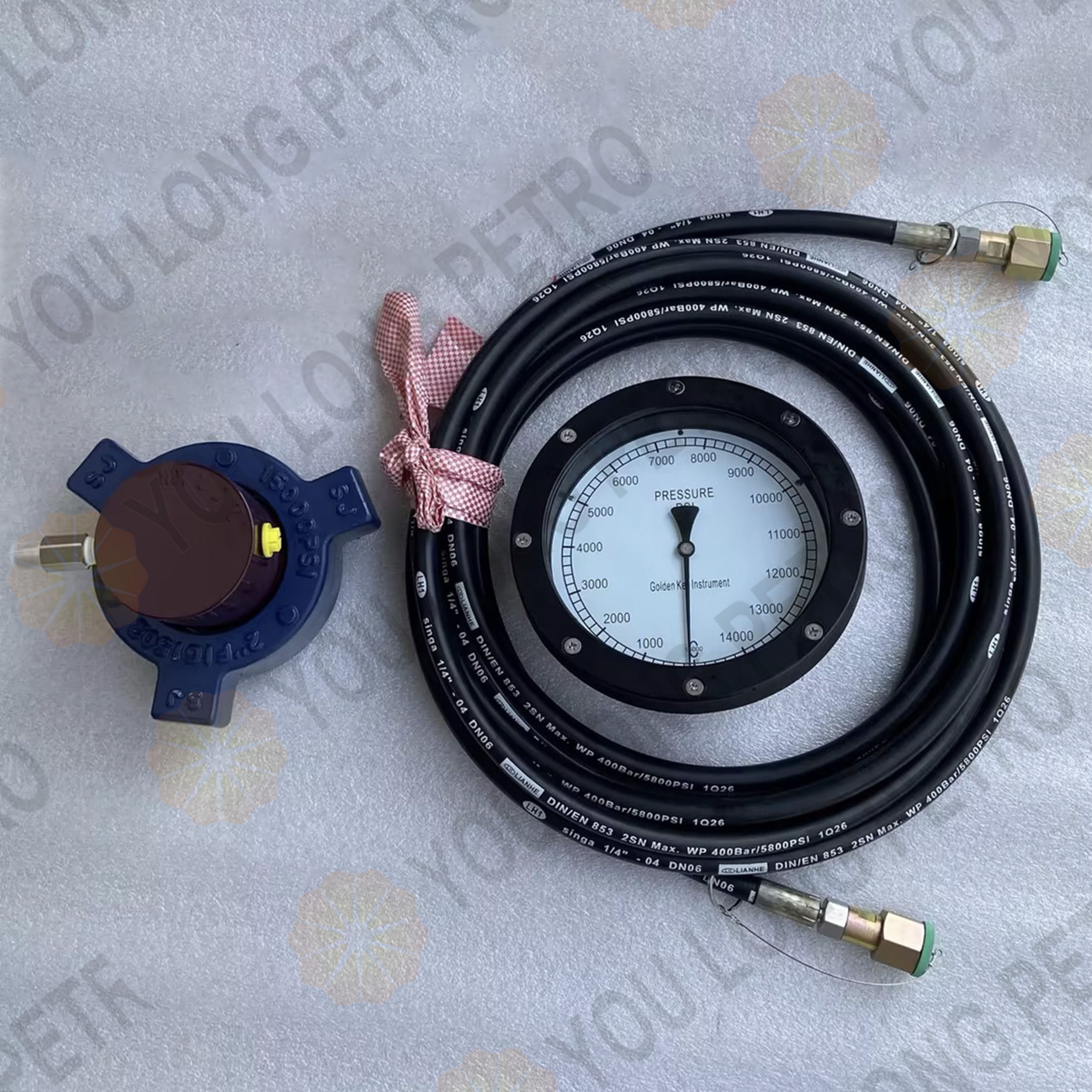
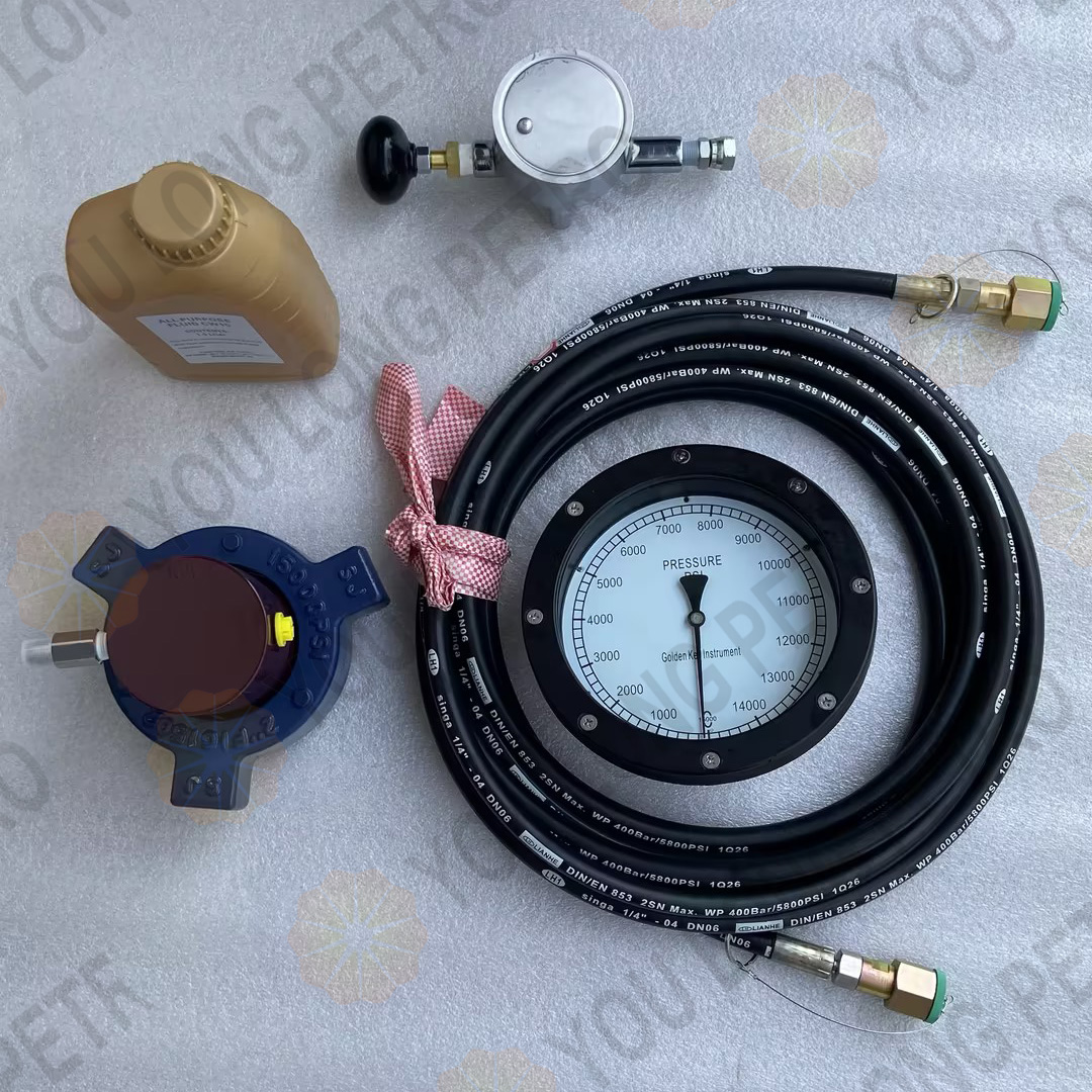
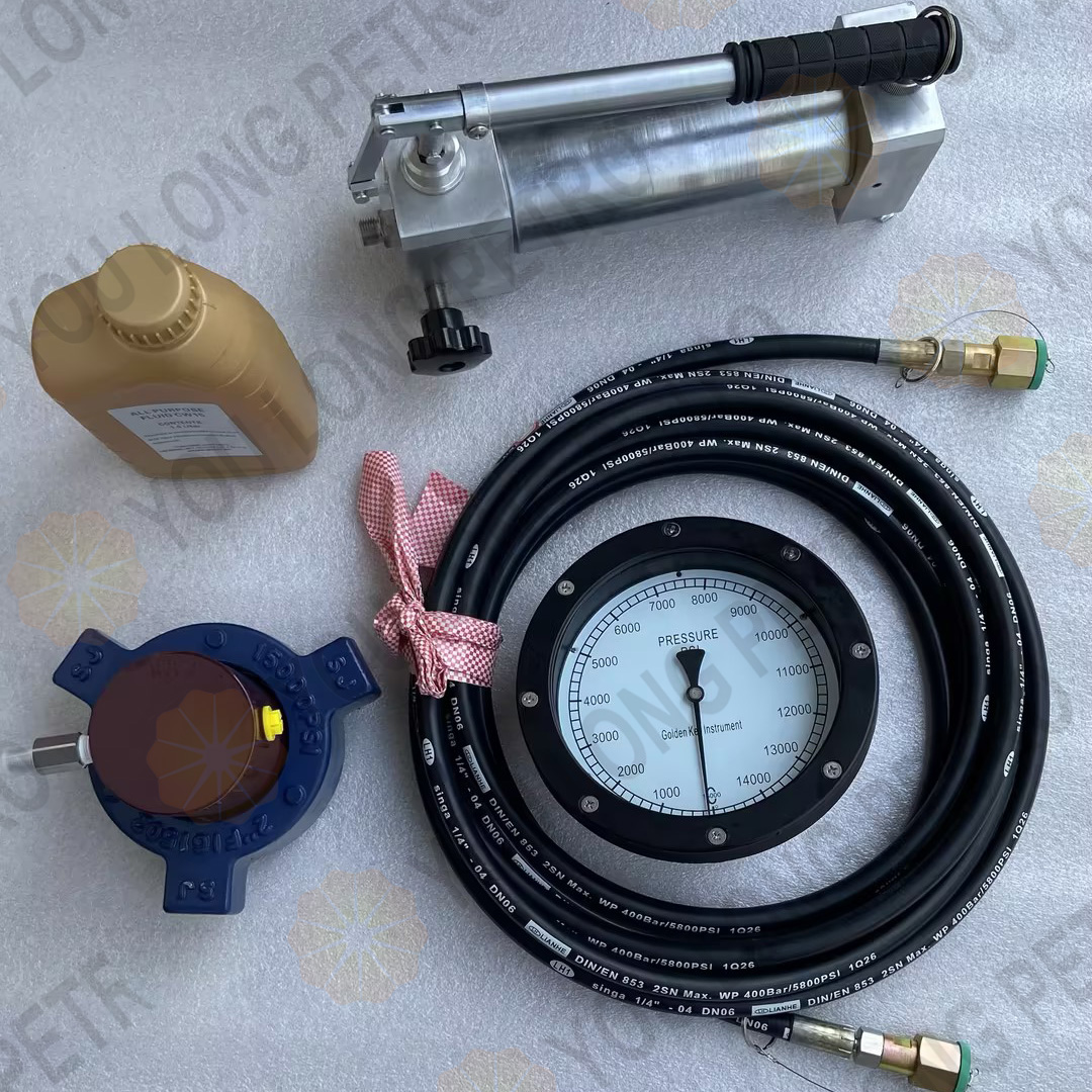
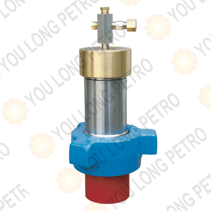
SZJ-LY.1-3 Diaphragm Type Sensor Standpipe Pressure
描述
SZJ-LY.1-3 Diaphragm Type Sensor Standpipe Pressure
1.System Composition
The unit consists of four interrelated components that work synergistically to achieve accurate pressure measurement and data transmission:
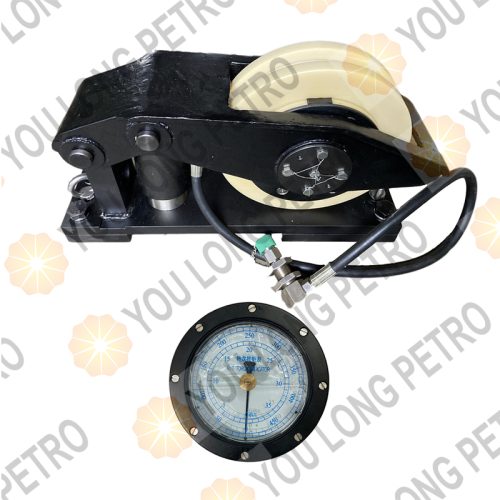
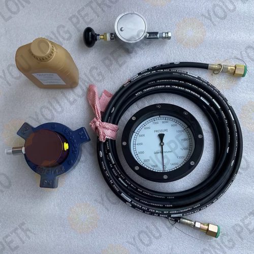
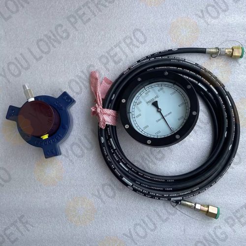
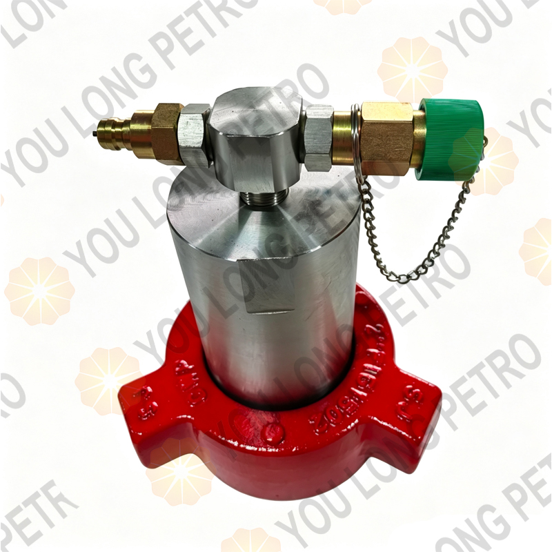
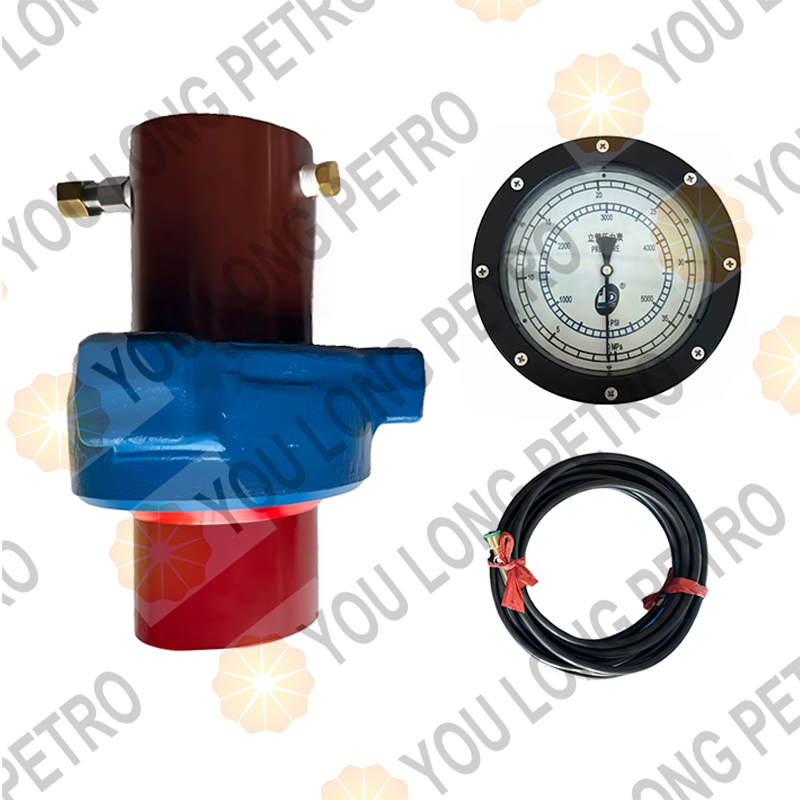
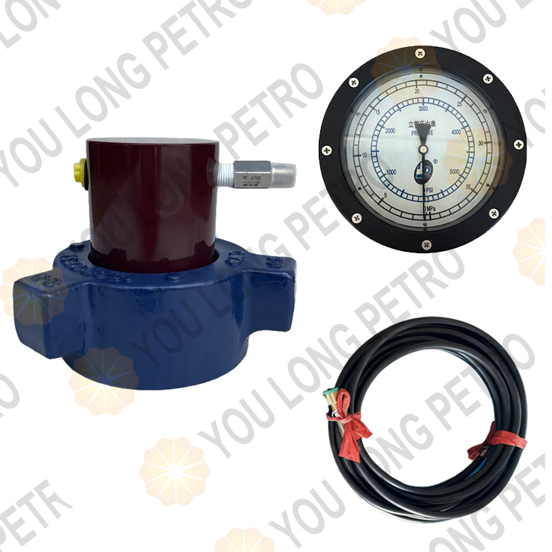
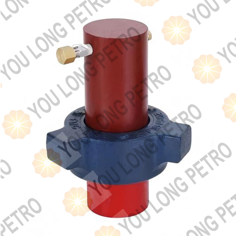
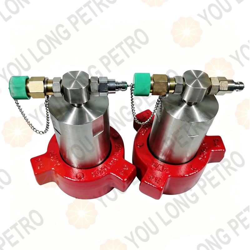
Standpipe Pressure Sensor: Two types are available-diaphragm-type (cup-type) and piston-type,Whatsapp+8615972752793 luben@youlongpetro.com https://www.youlongpetro.com both converting mud pressure into hydraulic pressure.
Standpipe Pressure Indicator: Installed in the driller’s console, it receives hydraulic signals and displays pressure values via a pointer.
Pressure Transmitter: Converts hydraulic pressure signals into 4~20 mA current signals for data acquisition and remote transmission.Whatsapp+8615972752793 luben@youlongpetro.com https://www.youlongpetro.com
Connecting Components: Include hydraulic hoses (10m or 15m), quick connectors, three-way joints, and sealing elements (O-rings, gaskets).
Figure 1: Schematic Diagram of Standpipe Pressure Measuring Unit (Including sensor, indicator, transmitter, hydraulic hoses, and data collector)
2. Working Principle
The unit operates based on hydraulic pressure transmission and mechanical-electrical signal conversion, What’s app +8615972752793 Luben@youlongpetro.comfollowing a precise workflow:
Pressure Sensing:
Diaphragm-type Sensor: Mud pressure in the standpipe acts on the elastic diaphragm (rubber cup) inside the sensor, compressing the internal hydraulic oil to generate pressure.
Piston-type Sensor: Mud pressure pushes the piston, Whatsapp+8615972752793 luben@youlongpetro.com https://www.youlongpetro.com transferring mechanical force to the hydraulic oil to form stable pressure.
Hydraulic Signal Transmission: The generated hydraulic pressure is transmitted to the bourdon tube of the pressure indicator through oil-resistant hydraulic hoses.
Mechanical Display: The bourdon tube deflects proportionally to the hydraulic pressure. This deflection is amplified by a mechanical mechanism (connecting rod, bevel gear), What’s app +8615972752793 Luben@youlongpetro.comdriving the indicator pointer to display the standpipe pressure value.
Electrical Signal Conversion: A three-way joint diverts part of the hydraulic pressure to the pressure transmitter, What’s app +8615972752793 Luben@youlongpetro.comwhich converts it into a 4~20 mA current signal (0 MPa corresponds to 4 mA, 40 MPa corresponds to 20 mA).
Data Processing: The current signal is transmitted to the data collector,Whatsapp+8615972752793 luben@youlongpetro.com https://www.youlongpetro.com then displayed on the driller’s console LCD/touchscreen and remotely sent to the duty room computer via wireless communication for recording and analysis.
3.1 Diaphragm-type Sensor Installation
Drill a hole in the standpipe and weld a nipple with 1 1/2 NPT male threads. Ensure the weld is sealed and free of leaks.What’s app +8615972752793 Luben@youlongpetro.com
Wrap PTFE tape around the sensor’s male union and screw it onto the nipple to form a tight seal.
Inject 45# transformer oil into the sensor through the self-sealing male connector. Stop when the diaphragm walls just touch (visual inspection). Overfilling will damage the diaphragm; underfilling will cause it to rupture during use.
Apply thread compound to the union, install the cylinder and female union, and tighten securely. Whatsapp+8615972752793 luben@youlongpetro.com https://www.youlongpetro.com A gate valve can be installed between the standpipe and sensor for convenient maintenance.
Ensure the sensor is oriented vertically upward to avoid measurement errors.
Figure 2: Installation of Diaphragm-type Standpipe Pressure Sensor

3.2 Piston-type Sensor Installation
Complete steps 1-2 as outlined for the diaphragm-type sensor.
Inject hydraulic oil into the sensor until the piston is fully extended (check via the observation port).
Install the piston assembly, tighten the wing nut, and verify the O-ring (34.5×3.55) is properly seated to prevent oil leakage.Whatsapp+8615972752793 luben@youlongpetro.com https://www.youlongpetro.com
Connect the pre-assembled hydraulic hose to the sensor’s quick connector.