描述
System Overview
1.1 System Block Diagram
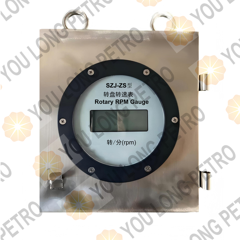
The SZJ-ZS type rotary table speedometer system consists of an input power supply (220/110VAC), a rotary table speed sensor, a connecting cable, a 220/110VAC power board, and a signal processing and display board. The power supply provides working voltage for the system, the sensor collects speed signals, and the signals are transmitted to the signal processing and display board through the cable for processing and speed display.
1.2 Technical Specifications
- Measurement Range and Error: Measurement range is 0 r/min ~ 300 r/min; Error is ≤ ±1.5% FS
- Power Supply: Operating voltage ranges from 85 VAC to 245 VAC, with a frequency of 47 Hz to 63 Hz
- Operating Environment: Temperature ranges from -30℃ to +70℃; Relative humidity is not more than 90% RH
1.3 System Composition and Working Principle
1.3.1 System Composition
The system is composed of a rotary table speedometer, a rotary table speed sensor, and a speed cable. The rotary table speedometer is a circular wide-temperature digital display meter. What’s app +8615972752793Luben@youlongpetro.comThe rotary table speed sensor adopts non-contact measurement and is composed of a proximity inductive switch and other components. The connecting cable is oil-resistant, corrosion-resistant, and flame-retardant, with explosion-proof, sealed, and waterproof connectors. The components of the sensor are shown in Figure 1 and Table 1 below.
Figure 1 Rotary Table Speed Sensor (Schematic Diagram)
The sensor is a modular structure, including a cover, O-ring, junction box, threaded sleeves, nuts, studs, probe housing, proximity switch, connector, and four-core socket, which are assembled in sequence to form a complete sensing unit.
Table 1 Rotary Table Speed Sensor Component List
| No. |
Part Number |
Component Name (English Translation) |
| 1 |
SZJ-ZS.1-1 |
Cover |
| 2 |
2-148 |
O-Ring 69.52×2.62 |
| 3 |
SZJ-ZS.1-2 |
Junction Box |
| 4 |
SZJ-ZS.1-3 |
Threaded Sleeve |
| 5 |
SZJ-ZS.1-4 |
Nut |
| 6 |
SZJ-ZS.1A-1 |
Stud |
| 7 |
SZJ-ZS.1-6 |
Threaded Sleeve |
| 8 |
SZJ-ZS.1-7 |
Nut |
| 9 |
SZJ-ZS.1A-2 |
Probe Housing |
| 10 |
– |
Proximity Switch |
| 11 |
SZJ-ZS.1-9 |
Connector |
| 12 |
– |
Four-Core Socket |
1.3.2 Working Principle
When a metal object passes near the sensing surface of the sensor, pulse signals are generated. What’s app +8615972752793Luben@youlongpetro.comThese signals are transmitted to the signal processing and display board of the rotary table speedometer through the cable. The board processes and calculates the current speed, and finally displays the result. The wiring diagram of the rotary table speed sensor is shown in Figure 2.
| Item |
Code |
Name |
| 1 |
SZJ-ZS.1 |
Speed Sensor |
| 2 |
SZJ-ZS.2 |
Tachometer |
| 3 |
SZJ-ZS.3 |
Explosion-proof Junction Box |
| 4 |
SZJ-ZS.1A |
Speed Sensor |
| 5 |
|
Thread Seal Tape |
Figure 2 Wiring Schematic Diagram of Rotary Table Speed Sensor
The four-core socket of the rotary table speed sensor has the following wiring specifications: The blue wire (signal wire) is connected to Pin 1 (Signal); The brown wire (+8.2V power wire) is connected to Pin 2 (8.2VDC); What’s app +8615972752793Luben@youlongpetro.comThe shielded wire is connected to Pin 4. The sensor core component is the proximity inductive switch, which is responsible for generating pulse signals based on the passing of metal objects.
- Installation, Commissioning and Operation
2.1 Sensor Installation
- Weld a metal sensing block at a suitable position on the transmission shaft leading to the rotary table. Drill a φ28 mm circular hole on the mounting bracket, align it with the sensing block, install the rotary table speed sensor, and maintain an induction distance of 5~10 mm. Rotate the transmission shaft to ensure that the sensor and the sensing block do not collide, as shown in Figure 3.
- When adjusting the distance between the sensor and the sensing plate, if sensor adjustment is required, first disassemble the junction box and remove the sensor terminals to avoid twisting the sensor wires. What’s app +8615972752793Luben@youlongpetro.comAfter adjusting the sensor, reconnect the wires in the reverse order of disassembly. The rotary table speed sensor is installed on the bracket of the rotary table transmission shaft. The method to adjust the distance between the sensor probe and the sensing plate is as follows: When installing the sensor, first ensure that the center of the sensor probe is aligned with the sensing plate. If not aligned, the on-site construction personnel should cooperate to slightly rotate the transmission shaft with tools or start the rotary table to rotate the transmission shaft at low speed, so that the sensing plate rotates at a certain angle to align with the sensor probe. Then tighten the nut that fixes the sensor to the mounting bracket, adjust the long stud of the sensor inward to make the probe touch the sensing plate, What’s app +8615972752793Luben@youlongpetro.comand then adjust the long stud backward by 3~5 turns to ensure that the distance between the probe and the sensing plate is maintained at 5~10 mm.
- After installation, apply sealant with filler at the mark “a” in Figure 3 to prevent rainwater from entering the junction box.
- Connect one end of the randomly equipped speed cable to the sensor, and the other end to the four-core socket of the circular meter head.
Figure 3 Installation Schematic Diagram of Rotary Table Speed Sensor
The sensor is fixed on the 120×10 mounting bracket. What’s app +8615972752793Luben@youlongpetro.comThe transmission shaft leading to the rotary table is equipped with a sensing plate. The distance between the sensor and the sensing plate is controlled at 5~10 mm, and the signal connector is connected to the sensor to realize signal transmission.
2.2 Installation of Rotary Table Speedometer
Install the rotary table speedometer at the corresponding position of the driller’s box or driller’s platform for easy observation by the driller, and connect the power cable and speed cable properly. The power cable is connected to the five-core socket, and the speed cable is connected to the four-core socket. What’s app +8615972752793Luben@youlongpetro.com The installation dimensions of the rotary table speedometer are as follows: the overall diameter is 163 mm, the inner diameter of the mounting hole is 145 mm, and there are 4 φ5.5 mm mounting holes evenly distributed (EQS).
2.3 Commissioning and Operation
The rotary table speedometer is mainly composed of a 110/220VAC power board and a signal processing and display board. The supply voltage is 110/220VAC. There are two aviation sockets on the back: the five-core socket is for power input, and the four-core socket is for speed signal input. What’s app +8615972752793Luben@youlongpetro.comIf there is a transmission ratio between the sensor installation position and the rotary table, the speed multiplication coefficient can be set as follows:
Turn off the power, remove the cover of the rotary table speedometer. The circular circuit board is the signal processing and display board, which is equipped with an 8-bit DIP switch (marked as “scale coefficient A” on the board, which is the multiplication coefficient) in binary. The multiplication coefficient range is 0.00~2.55. For example, to set the multiplication coefficient to 1.00, first multiply by 100 to get 100, which is converted to binary as 64H. What’s app +8615972752793Luben@youlongpetro.comThe DIP switch setting is shown in Table 2. For another example, to set the multiplication coefficient to 0.301, first multiply by 100 to get 30.1, take the integer part 30, which is converted to binary as 1EH. The DIP switch setting is shown in Table 3.
Table 2 DIP Switch Setting for Multiplication Coefficient 1.00
| Mark |
1 |
2 |
3 |
4 |
5 |
6 |
7 |
8 |
| Setting |
OFF |
ON |
ON |
OFF |
OFF |
ON |
OFF |
OFF |
Table 3 DIP Switch Setting for Multiplication Coefficient 0.301
| Mark |
1 |
2 |
3 |
4 |
5 |
6 |
7 |
8 |
| Setting |
OFF |
OFF |
OFF |
ON |
ON |
ON |
ON |
OFF |
In addition, there is a button switch on the circuit board. When pressed, the instrument is in the measurement state; when popped up, What’s app +8615972752793Luben@youlongpetro.comthe LCD displays the multiplication coefficient (displayed as Px.x.X, where X.xx is the coefficient value, taking two decimal places. For example, the coefficient 1 is displayed as P1.0.0), which is convenient for checking whether the multiplication coefficient setting is correct.
What’s app +8615972752793Luben@youlongpetro.comCalibration of the rotary table speedometer: Pop up the button switch, the LCD displays the multiplication coefficient. First set the coefficient A to 1.00, press the button switch to put the instrument in the measurement state. Make a clear mark on the rotary table to count the number of rotations when the rotary table is rotating. Start the rotary table at a low and uniform speed, and at the same time use a stopwatch or other timing device to start timing. What’s app +8615972752793Luben@youlongpetro.com Count the number of rotations X of the rotary table in 1 minute according to the mark on the rotary table, and record the rotary table speed display value Y on the speedometer at this time (if there is no display, the distance between the sensor and the metal sensing plate exceeds 10 mm, or the material of the sensing plate is not a magnetic conductive material such as metal, or there is a wiring problem); Use X/Y = coefficient A, and then reset the value of A.
After setting the multiplication coefficient, What’s app +8615972752793Luben@youlongpetro.com install the speedometer cover in the reverse order of disassembly. When tightening the 6 screws, they should be tightened symmetrically and evenly with moderate force to avoid glass breakage.
- Maintenance, Troubleshooting
3.1 Maintenance
- During the instrument relocation, please turn off the power first, then remove all cables from the sensor and screw on the protective cap.
- The cable laying should follow the principle of not hindering the on-site operation of the wellsite staff, not being easily hit or damaged, What’s app +8615972752793Luben@youlongpetro.comand being safely and reliably erected.
- Frequently check the distance between the sensing surface and the sensing plate to avoid damage to the sensing surface due to looseness after vibration.
- Frequently check whether each connector is loose and whether the cable is broken.
- Care should be taken not to contaminate the sensing surface with metal chips or oil stains containing metal chips, What’s app +8615972752793Luben@youlongpetro.comso as to avoid magnetic short circuit and sensor misoperation. The installation position should avoid direct sunlight as much as possible to improve its reliability.
- The voltage of the sensor signal terminal to the ground should be 3.75V. If it is too large, please pay attention to observe whether the displayed data is normal.
3.2 Fault Causes and Troubleshooting Methods
When solving the speed parameter problem, What’s app +8615972752793Luben@youlongpetro.comthe signal processing and display board must work normally first. After the rotary table speedometer is powered on, the indicator light of the signal processing and display board will flash regularly. If it cannot work normally, the circuit board is faulty.
If the speed display is incorrect or there is no display, check from the power supply, the sensor itself, the signal processing and display board, and the scale coefficient (assuming the signal processing and display board is normal).
For the problem of large fluctuation of speed parameter display:
- Check the corresponding cable. What’s app +8615972752793Luben@youlongpetro.comThe inner shield layer of the cable must be grounded, that is, connected to Pin 4 of the aviation plug, and other pins must also be reliably soldered.
- Check the wiring in the sensor junction box. The wiring must be firm and free of looseness. Check that the distance between the sensor probe and the sensing block should not be too close or too far.
- Check whether the corresponding wiring in the rotary table speedometer is reliable.
- If the above methods still cannot solve the problem, the signal processing and display board needs to be replaced.
3.3 Precautions
- Do not disassemble the instrument with power on.
- Do not rinse the instrument with water.
- The cable shall not be squeezed or worn, and shall be replaced in time if it is broken.What’s app +8615972752793Luben@youlongpetro.com
- After the sensor is initially installed on site, the rotary table speed multiplication coefficient A has been set according to the transmission ratio of the rotary table. If the installation position is changed and the transmission ratio of the rotary table is changed, the multiplication coefficient A needs to be recalibrated.
- All shielded cables shall not pass through the conduit or open trunking together with other power cables, and shall also avoid being close to high-power equipment.
SJPETRO#RGPETRO#DFXK#ZYT#BPMCO#LANSHI#NOV#NATIONAL OILWELL WARCO#KERUI#HH#HONGHUA#BAOJI#BOMCO#CPTDC#SJ
Contact info
What’s app +8615972752793
Luben@youlongpetro.com
You Long Petroleum Machinery Spares ltd.(YOU LONG PETRO) engages in the export of the petroleum equipment and materials and provides materials and equipment for CNPC and SINOPEC’s overseas projects. Established in 2003,YOU LONG PETRO has started the manufacturing and supplying of petroleum materials and equipment since 2003.YOU LONG PETRO has provided its products and services to 36 countries and regions across the globe.YOU LONG PETRO’s export performance has come out top in central enterprises in successive years and it has been acknowledged as China’s largest supplier of petroleum and petrochemical materials,which is based on design,production,sale and technical service.Our products are completely interchangeable with the following enterprises.
The products are asfollows:
1,Drilling mud pump parts(Bomco, HH, Rongsheng, RJ etc.)
2,Oil drilling rig parts & Workover rig parts (RG, SJPETRO,DFXK etc),
3,Parts for hydraulic disc brake (BPM,Boke,Bomco,RG)
4,ATDPush-plate clutch What’s app +8615972752793 Luben@youlongpetro.com and parts & WCB2 Auxiliary brake parts.
5,ZQ Drill pipe power tongs and parts,TQ Series of casing power tongs and parts.
6,CB/LT series:Air tube clutch and parts.
7,Agent products such as: Bearings, Chains, Cardan shaft,V-belt,engine etc
#drilling #rig #mudpump #liner #drillingrig #oilwell #equipment #vendor #supplier #oilrig #hopps #China #factory #pump #petroleum #oil #gas #valve #piston #nov #gardnerdenver #bomco #drillmec #weatherford #ideco #spm #emsco #Halliburton #Schlumberger #BakerHughes
#cylinder #cylinderliner #drillingrigs #drillingcrew #oilfield #waterwell #oilwell #suppliers #parts #triplex #duplex #varco #elliswilliams #lewco #rongsheng #lsnow #russian #halliburton #upetrom #opi #americanblock #soilmec #tfi #BJPacemaker #FZFXZ #FGFXG #FDFXX #FDFXD #FYFXX #FYFXD #FOFXO #FKFXK #FCFXX #FCFXO #TEE #THE #PZ7 #PZ8 #PZ9 #PZ10 #PZ11 #PZ2000 #PZ2400 #UNB600 #UNBT1180 #UNBT950 #UNBT650 #NBT300 #MP5 #MP8 #MP10 #MP13 #MP16 #F500 #F800 #F1000 #F1300 #F1600 #F2200 #DB550 #T1000 #7P50 #8P50 #9P100 #10P130 #12P160 #14P200 #14P220 #JWS340 #JWS400 Contact info What’s app +86 15972752793 Luben@youlongpetro.com #G700 #A560PT #A600PT #A850PT #A1100PT #A1400PT #A1700PT #TWS2500 #TWS400 #TWS600 #T500 #T800 #T1000 #T1300 #T1600 #7T450 #7TS600 #8T800 #9T1000 #9T1300 #10T1300 #12T1600 #14T2200 #12T1600GD #W440 #W446 #E447 #E2200 #TWS600S #TWS2250 #TWS2500 #5ZB2500 #5ZB2800 #HT400 #HT446 #3PN700 #3PN1000 #3PN1300 #3PN1600 #3PN2000 #30D #350GD #500DC #700HDL #1000HDL #K800 #K1000 #K1300 #K1600 #K2000 #K2200 #7T500 #7T508 #8T650 #RSF500 #RSF800 #RSF1000 #RSF1300 #RSF1600 #HHF500 #HHF800 #HHF1000 #HHF1300 #HHF1600 #HHF2200 #QF1600 #3NB500 #3NB800 #3NB1000 #3NB1300 #3NB1600