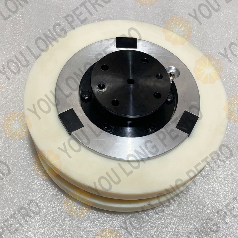
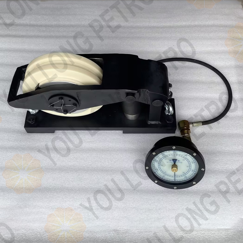
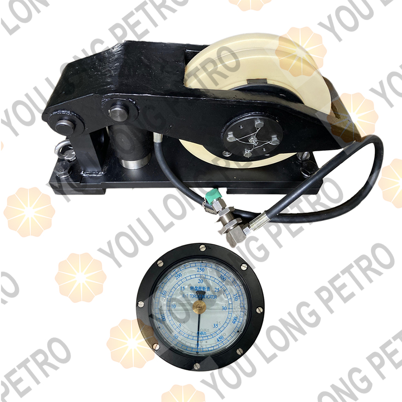
SZJ-ZN.4.1 Ldler Assembly For Rotary Torque Sensor
描述
SZJ-ZN.4.1 ldler Assembly For Rotary Torque Sensor
1. System Overview
1.1 Core Function
The SZJ-ZN Rotary Torque Measuring System is a specialized device for mechanical drilling rigs driven by rotary chains. What’s app +8615972752793 Luben@youlongpetro.comIt indirectly measures the torque exerted by the rotary table on the drill stem by detecting the pull force of the tight side of the rotary drive chain, providing real-time and accurate torque data for drillers to monitor drilling operations.
1.2 Main Technical Specifications
| Parameter | Specification |
| Working Temperature | -30℃ ~ 65℃ |
| Relative Humidity | 0% ~ 90% |
| Measuring Range | 0 ~ 45 kN·m (displayed as 0 ~ 500 scales) |
| Measurement Error | ≤ ±2.5% FS (Full Scale) |
| Pressure Transmission Medium | 45# Transformer Oil |
1.3 System Composition
The system consists of four key components that work synergistically to ensure reliable performance:
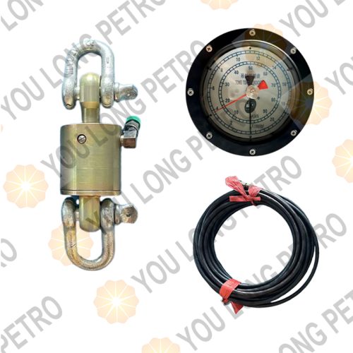
Idler-Type Rotary Torque Sensor: The core detection component, which converts chain pull force into hydraulic pressure.What’s app +8615972752793 Luben@youlongpetro.com It is available in specifications matching different chain types (single/dual row, 1.5″/1.75″/2″ pitch) to fit various drilling rigs.
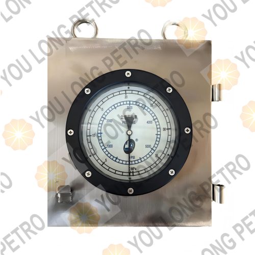
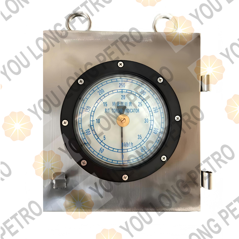
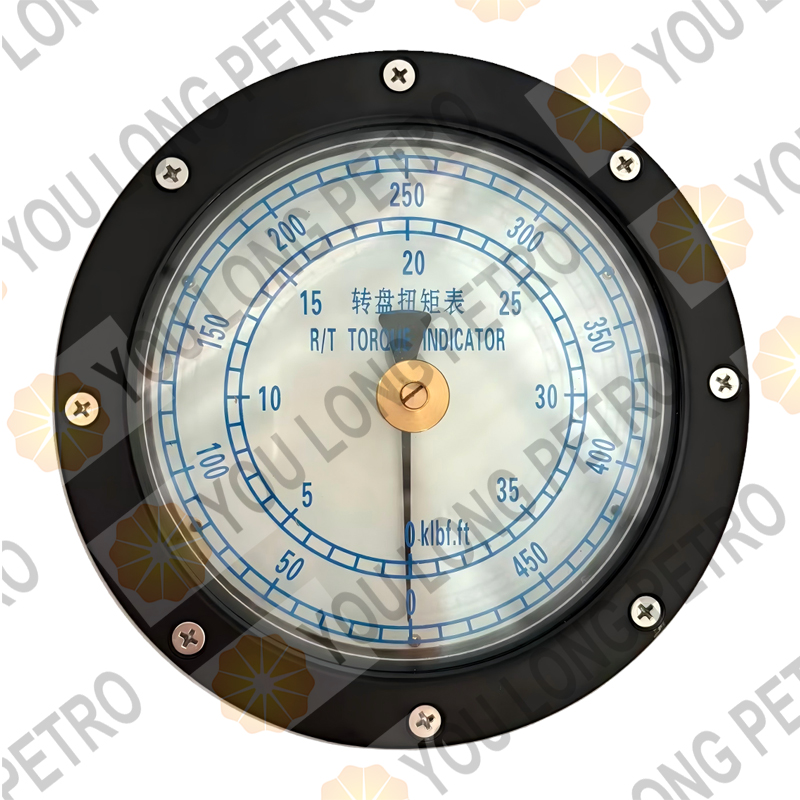
Rotary Torque Gauge: Installed in the driller’s console, it receives hydraulic signals and displays torque values via a pointer.What’s app +8615972752793 Luben@youlongpetro.com It features a zero-adjustment knob for calibration.
Damper Valve: Reduces pointer vibration of the torque gauge, ensuring stable and readable measurements by regulating hydraulic fluid flow.
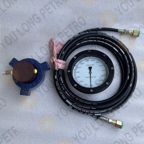
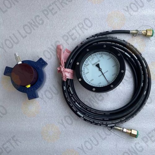
Hydraulic Connecting Hoses: Transmit hydraulic pressure between the sensor and the gauge.What’s app +8615972752793 Luben@youlongpetro.com Two lengths (10m and 15m) are available for different installation scenarios.
Figure 1-1: Schematic Diagram of SZJ-ZN Rotary Torque Measuring System (Including idler-type sensor, torque gauge, damper valve, and hydraulic hoses)
Hydraulic Fitting Installation: Mount the hydraulic elbow on the chain box to guide the sensor’s hydraulic hose outwards.

Installation Drawing of Idler-Type Rotary Torque Sensor
| 1 | SZJ-ZN.1-9 | Installation board |
| 2 | GB32.1-88 | Eye bolt M8×18 |
| 3 | GB32.1-88 | Eye bolt M8×40 |
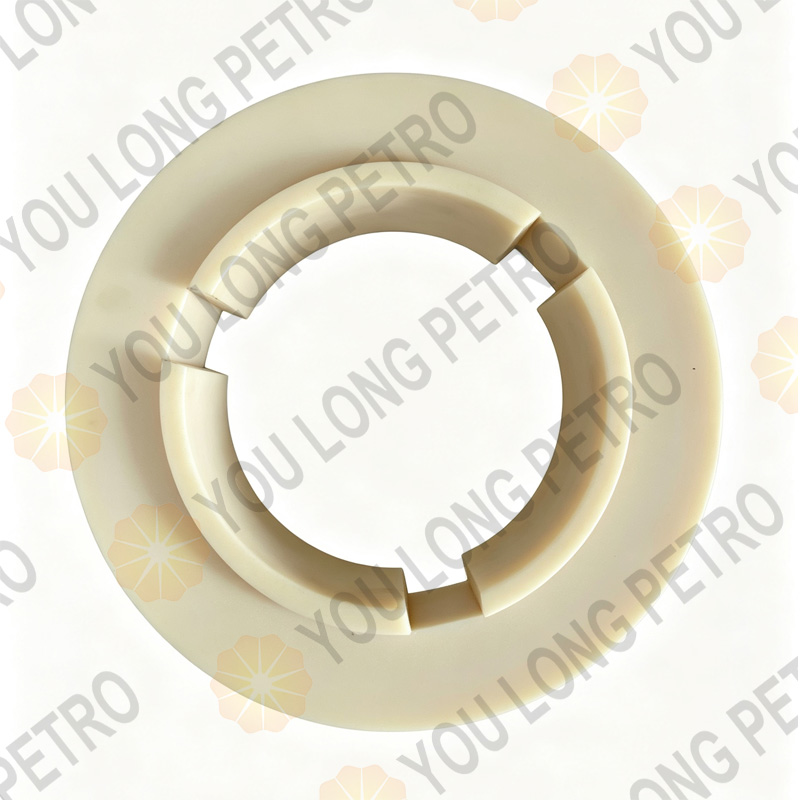
| 4 | SZJ-ZN.4.1 | ldler assembly |
| 5 | SZJ-ZN.4-2 | Support arm |
| 6 | SZJ-ZN.1A-5 | Pin shaft |
| 7 | SZJ-ZN.4.4 | Piston assembly |
| 8 | SZJ-ZN.1.8 | Support bracket |
| 9 | GB825-76 | Lifting bolt M12 |
| 10 | SZJ-ZN.1-16 | Spacer |

2.2 Installation of Rotary Torque Gauge
Fix the driller’s console (equipped with the torque gauge) in front of the driller to ensure clear visibility of the dial.
Connect the hydraulic hose (tagged “rotary torque gauge”) to the corresponding connector on the driller’s console.
Pressure Test: Connect a piston pressure gauge to the torque gauge, What’s app +8615972752793 Luben@youlongpetro.comgradually apply 0~6MPa pressure in 1MPa increments. Verify the gauge pointer moves smoothly within the 0~500 scale range, with no oil leakage at connections. Repeat the test during pressure reduction.
2.3 Hydraulic Hose Connection
Connect one end of the 10m or 15m hydraulic hose (tagged “rotary torque gauge”) to the sensor’s built-in hose, Whatsapp+8615972752793 luben@youlongpetro.com https://www.youlongpetro.com and the other end to the matching connector at the back of the driller’s console.
Open the air exhaust valve on the driller’s console. Inject oil from the console’s oil injection port to purge air from the copper and hydraulic hoses (check for bubble emission). Close the valve once air is fully exhausted.
2.4 System Adjustment
Fully open the damper valve to ensure unobstructed hydraulic flow.
Lift the chain to avoid contact with the sensor’s idler. What’s app +8615972752793 Luben@youlongpetro.comAdjust the gauge knob to set the pointer to zero, then lower the chain.
Connect a hand pump to the torque gauge’s oil injection port (inside the driller’s console).Whatsapp+8615972752793 luben@youlongpetro.com https://www.youlongpetro.com Inject oil while opening the air exhaust valve to purge residual air. Close the valve and continue injecting until the gauge reads 50~70 (initial no-torque value).
Lock the rotary table brake, gently engage the rotary table clutch to generate large chain pull force. The gauge should read 300~400. If not, add or drain oil and repeat the adjustment.
During operation, slowly adjust the damper valve (clockwise to reduce opening) to minimize pointer vibration and ensure stable readings.
3. Maintenance and Important Notes
3.1 Regular Maintenance
Before moving the system, turn off the power, disconnect all hoses, and install protective caps on connectors to prevent contamination.
Route hoses safely to avoid collision, damage, or interference with drilling operations.
Regularly inspect the gap between the sensor’s induction surface and the chain, What’s app +8615972752793 Luben@youlongpetro.comand tighten loose connections caused by vibration to prevent component damage.
Check hoses for cracks and connectors for looseness; replace damaged hoses promptly.
Keep the sensor’s induction surface clean; avoid contamination by metal shavings or oil containing metal particles to prevent magnetic short circuits.
| Item | Code | Name |
| 1 | SZJ-ZN.2 | Rotary Table Torque Meter |
| 2 | SZJ-ZN.2A | Rotary Table Torque Meter |
| 3 | SZJ-ZN.1 | Rotary Table Torque Sensor |
| 4 | SZJ-ZN.1.2 | Idler Pulley |
| 5 | SZJ-ZN.1.2-1 | Idler Pulley |
| 6 | SZJ-ZN.1.1 | Rotary Table Torque Pipeline |
| 7 | SZJ-ZN.1A | Rotary Table Torque Sensor |
| 8 | SZJ-ZN.1A.1 | Idler Pulley |
| 9 | SZJ-ZN.1A.1-1 | Idler Pulley |
| 10 | SZJ-ZN.1.2-1t | Idler Pulley (24A/28A) |
| 11 | SZJ-ZM.6-1 | Four-way Joint |
| 12 | SZJ-ZN.4 | Rotary Table Torque Sensor |
| 13 | SZJ-ZN.4.1 | Idler Pulley Assembly |
| 14 | SZJ-ZN.4.1-1 | Idler Pulley (32A) |
| 15 | SZJ-ZN.4.1-1t | Idler Pulley (24A/28A) |
| 16 | KTB600-10 | 10 MPa Pressure Transmitter |
3.2 Key Notes
Sensor specification must match the chain type (pitch, single/dual row). Mismatched specifications will cause system failure.Whatsapp+8615972752793 luben@youlongpetro.com https://www.youlongpetro.com
The chain box inner width must be greater than the sensor’s 160mm width to avoid friction between the sensor and box walls.
Hand pumps (Model: Q/JY250-84, with 5m hydraulic hose) and 45# transformer oil are essential accessories,What’s app +8615972752793 Luben@youlongpetro.com identical to those used for weight indicators. Prepare them as needed.
Do not disassemble the instrument while powered on to avoid electric shock or component damage.